
Inclinometer / Tilt Meter for Heliograph Aimer : 無料・フリー素材/写真
Inclinometer / Tilt Meter for Heliograph Aimer / signal mirror

| ライセンス | クリエイティブ・コモンズ 表示 2.1 |
|---|---|
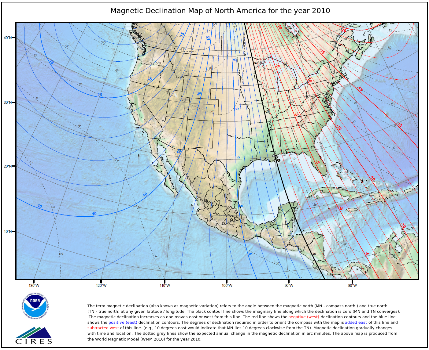
| 説明 | Ideally, this device will make rapid work of contacting stations that are invisible in the haze. The idea is to make horizontal sweeps around the computed compass bearing, using this tilt meter to set the beam at the computed target elevation, then repeat the horizontal sweeps at 0.2 degrees above and below that elevation to account for measurement error.We'll see - the next contact I make successfully this way will be the first. But it seems like a good idea. This photo has annotation rectangles. If you hover your mouse over the photo, you will see annotation rectangles - move your mouse cursor into a rectangle to read the note for that rectangle. Flickr dropped support of annotation rectangles - sorry.This approach doesn't require this specific device. An accurate tilt meter can be made cheaply with no more than transparent tubing and water, but if you can borrow an electronic level like this, it is likely to be less trouble. There are cheap inclinometer/clinometer/tiltmeter/digital level apps for the iPhone and Android, if that's something you have or can borrow.. iPhone apps typically have 0.1 deg resolution, and would likely give decent results if you use the "measure, rotate 180 deg, measure, average" approach to removing bias.I find it difficult to read the iPhone display in full sun, and was hoping for more accuracy, so I bought this. Your priorities may vary. Note that asking around may turn up something like this that you can borrow, rather than spending money on something you'd rarely use. One solution to reading the iPhone display in sun is to bring a packable lightshade.The markings on the tilt meter I am using here may be hard to read even in the full resolution photo. You should be able to get one for under $30, with shipping, and it is rated for 0.2 degree elevation accuracy and 0.05 deg resolution. I got mine on Ebay, but it is sold widely - at Amazon this is the iGaging AngleCube Digital Level.Why a tilt meter?One challenge in the Scouting long-range mirror signaling activity Operation On-Target is haze. Ideally, you would be able to see the target station, and direct your flashes based on that sighting using one of the various types of mirror aimer, such as the crosshairs mirror aimer that is the subject of this Flickr set. In practice, the more distant stations are likely to be invisible in the haze.In many cases, contact is possible, since the bright reflected sunlight of a mirror flash is far stronger than the diffusely reflected light from the haze. The classic approach is to signal in the approximate direction of the other station, hoping that they will see your flash. Once they see your flash, they will better know where to aim their flash, and hit you. You, seeing their flash, correct, and you hit each other more and more often. With the basic mirror aimer, the azimuth and elevation settings "remember" the direction to the target, so once the crosshairs have been centered on the other station, hitting it is easy, since even if you take a break, the crosshairs will still point to the station.However, scanning for the station in the first place can be tricky, since the reflected sunbeam is only 0.5 degrees wide - a miss of 0.25 degrees is the difference between a perfect hit and a clean miss. You want to start scanning close to the target.To maximize your chance of success, you want to determine the azimuth bearings from your planned station to the other planned stations. Ideally, you do this before the day of the event, since you will be very busy during the event itself. This task will call on many of the skills in the Orienteering Merit Badge. and the Surveying Merit Badge. Given the station locations, the bearings can be determined graphically from a topographic map, or calculated from the station latitudes and longitudes from a map, database, or GPS readings. Bearings calculated from latitude and longitude are "true" bearings to North, but you will usually be using a compass in the field to determine azimuth, so you will want to convert these true bearings to magnetic bearings.The difference between true and magnetic bearings is Magnetic Declination, which changes with location and (less quickly) with time. Many maps will provide the magnetic declination, or you can use the NOAA Magnetic Declination Map. For more precise estimates, you can use the NOAA magnetic declination calculator.However, the compass bearing you take in the field is unlikely to be accurate to our desired 1/4 degree. Compasses are usually rated for 1 degree accuracy at best, and local magnetic influences add error as well (scan yourself with a compass to root out any disturbing ferrous material in your sunglasses, watch, buttons, belt buckle, etc., that might disturb your compass reading, and take your bearings when at least 10 feet from cars, metal fence posts, etc., and in several locations to guard against metal that you cannot see.)Even with all this, you are likely to have a fair amount of uncertainty in your elevation. An accurate tilt meter can be made cheaply with no more than transparent tubing and water, but if you can borrow an electronic level like this, it is likely to be less trouble.Calculating the elevation angle to your distant station is a similar process to calculating the bearing, except that you will need the elevation of each station as well as the latitude and longitude. To first order, the elevation is just a function of the range and the difference in heights. It gets a bit messier if you wish to be more accurate, for the atmospheric refraction term is a function of the altitude and air temperature. For the moment, I'm taking the lazy way out, and entering my intended station in the main ("testbed") page of HeyWhatsThat.com ( for example, here is Santiago Peak, and clicking in the "show alts" checkbox at the bottom of the scrolling peak list at right to have it compute the elevations. There are many more peaks stored that don't appear in the scrolling list - if you click on the "more features" on the map, you will see them as blue crosses in the higher magnification views, and clicking on a blue cross will reveal its elevation. Another nice planning Web application, www.Peakfinder.org, will show elevations if you click on the "binoculars" icon (you can see the view from Santiago here) I've found that the "rollover" from one elevation to another in Peakfinder occurs at the halfway point (that is, when the readout shifts from 0 deg to -1 deg, you are at -0.5 deg), so you can use this with interpolation, but that's not nearly as handy. |
| 撮影日 | 2013-05-11 14:49:53 |
| 撮影者 | signal mirror |
| タグ | |
| 撮影地 | |
| カメラ | DMC-FZ28 , Panasonic |
| 露出 | 0.002 sec (1/500) |
| 開放F値 | f/7.1 |