
Soundcard Interface using 2N2222s : 無料・フリー素材/写真
Soundcard Interface using 2N2222s / JCHaywire
| ライセンス | クリエイティブ・コモンズ 表示-継承 2.1 |
|---|---|
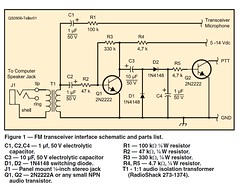
| 説明 | A Sound Card Interfacefor FM TransceiversHoward “Skip” Teller, KH6TYW hile looking for a way to enablemore people to use the Narrow BandEmergency Messaging System (seewww.w1hkj.com/NBEMS/) on 2 meters, itbecame clear that the lack of VOX in mostFM-only transceivers was a serious stumblingblock. That’s because NBEMS relieson sound-card-based software. In addition tocreating the audio signal for transmission, thesoftware must also have access to a hardwareinterface that would allow it to switch the FMtransceiver into transmit and back to receive.You could use a commercial or home brewsound card interface for this application, butmany of these interface devices requirecomputer serial (COM) ports to function. Ifyour computer lacks a COM port (most newlaptops don’t have them), you’d have to use aUSB port, which, in turn, requires a USB-to-Serial converter to create a virtual serial portfor the digital software to use.I decided to try an easier, more elegantapproach, one that would work not onlywith NBEMS software, but also with othersound-card modes such as DominoEX withthe free Fldigi software (www.w1hkj.com/Fldigi.html). DominoEX in particular hasdemonstrated intriguing performance whenused on VHF FM, rivaling even “weak signal”SSB in some instances (see the sidebar“Try “Weak Signal” Digital FM”). Of course,you could also use this interface for soundcardpacket radio with AGW Packet Engine(www.sv2agw.com/ham/agwpe.htm) software.No COM or USB ports required!Let the Audio do the WorkMost digital modes work by modulatingthe transceiver with an audio tone, and thattone can also be used to switch the transceiverin and out of transmit automaticallyby using a voice-operated switch (VOX)circuit.First the audio tone must be amplifiedto get enough signal to detect and switcha transistor for the transmit/receive line. Inorder to amplify the tone, there needs tobe some convenient source of dc voltageto power the amplifier. A review of theschematic diagrams for modern transceiversrevealed that most have a voltage on thepush-to-talk (PTT) line that can power theswitching transistor. For those transceiversthat have a DTMF tone generator built intothe microphone, there is also 8 Vdc availableat the microphone jack, and this voltage canbe used to power the necessary amplifier asshown in Figure 1.2 June 2009Try “Weak Signal” Digital FMHere’s an application for your newly built interface that you and your friendscan try right away. All you need are ordinary 2-meter FM voice transceivers.Tell everyone to go to www.w1hkj.com/Fldigi.html and download andinstall Fldigi. This free multimode software package is available for bothWindows, MacOs and Linux operating systems. Once everyone has theirsoftware running successfully, set up some times to meet on the air. Onesuggested frequency is 145.00 MHz, simplex. (When selecting a frequency,always follow the band plans that are in effect in your area and listen carefullybefore transmitting.)When you’re ready, fire up Fldigi, choose either the DominoEX8 orDominoEX4 modes and start enjoying keyboard-to-keyboard text conversations.What you’re likely to discover is that you can span a remarkable rangewith this setup, much farther than FM voice alone.If you really want to push the envelope, use 50 W FM transceivers (or add“brick” amplifiers to the radios you are using now) and horizontally polarizedYagi antennas (short 3 or 4 element Yagis will do). Depending on the terrain inyour area, you may find that you can have DominoEX chats over astonishingdistances! — Skip Teller, KH6TYFigure 3 — A version of the VOX interface using the circuit board provided bythe author.The transmit audio from the sound cardSPEAKER or LINE OUT jack is fed into a600:600 Ω isolation transformer to eliminatethe possibility of hum or ground loopsbetween the computer and transceiver. Theisolated audio signal is passed through C1and attenuated to microphone levels by R1before reaching the transceiver microphoneinput. A portion of the signal is also coupledvia C2 and R2 to the base of Q1, where itis amplified to a level of several volts. Thisac voltage is peak detected by D1 and D2,which form a voltage doubler, generatingenough voltage across C4 to cause thebase of Q2 to go high and switch the PTTline to ground, thereby switching the transceiverinto transmit mode. When the tone isstopped by the software, Q2 is turned off andthe transceiver returns to receive state.ConstructionThere are only a few parts to the interface,so one method is to use “ugly bug” constructionand handwire the circuit on a piece ofcopper-clad circuit board material. A smallRadioShack project enclosure was used tohold the interface circuit board, mount thestereo audio input jack so it is insulated fromthe circuit board, and protect the interfacecircuitry (see Figure 2).If you’d prefer a cleaner approach, afiberglass circuit board with plated-throughholes, parts legend and solder mask isavailable (Figure 3). Send $5 with a selfaddressed,stamped envelope to: KH6TY,335 Plantation View Ln, Mount Pleasant,SC 29464.The interface terminates in a 4-wirecable and a microphone connector to matchwhatever transceiver is going to be used.For transceivers using the plastic RJ-45 orRJ-12 microphone jacks, existing CAT-5 ortelephone jumper cables can be cut in half,eliminating the need to purchase a crimpingtool.InstallationInstalling the VOX interface couldn’tbe easier. A standard stereo audio patchcable is connected between the sound cardSPEAKER or LINE OUT jack and the stereojack on the interface, and the interfacemicrophone connector is plugged into thetransceiver microphone jack. For receiveaudio, a separate cable must be connectedbetween the sound card MICROPHONE orLINE IN jack and the transceiver earphone/external speaker jack.Using the Windows Volume Controlpanel, the WAVE and VOLUME CONTROLsliders are adjusted while running the softwarein the transmit or calibrate mode untilthe transceiver goes into transmit, and thenraised a little higher. This should provide theright level of audio for the transceiver. If thelevel is too low, R1 can be reduced in valueto increase the audio drive to the transceiver.Although I designed this circuit for digitaloperating with FM transceivers on theVHF and UHF bands, nothing would stopyou from putting this interface to work forHF digital as well. All you need to do is supply5 to 14 V dc for the amplifier stage.Howard (“Skip”) Teller, KH6TY, is an ARRLmember and was first licensed in 1954. Hereceived his commercial First ClassRadiotelephone license in 1959 and worked hisway through college as chief engineer of severalradio stations. He holds a BS degree in electricalengineering from the University of SouthCarolina and is retired from running a factory inTaiwan, where he manufactured the weatheralert radio that he originated in 1974 and is stillsold by RadioShack and many other companies.Skip enjoys developing digital software, such asDigiPan and NBEMS, designing 2 meter transceiversand antennas. He is currently studyingthe potential of working 2 meter DX on FM usingdigital modes. You can contact Skip at 335Plantation View Ln, Mt Pleasant, SC 29464;KH6TY@comcast.net. |
| 撮影日 | 2009-11-10 00:40:16 |
| 撮影者 | JCHaywire |
| タグ | |
| 撮影地 |